
Most LANs use some form of cable as their network medium. Although there are many types of wireless media, cables are more reliable and generally provide greater transmission speeds than other media. Data-link layer protocols often provide more than one cable specification to choose from. Each specification includes the type of cable to use, the cable grade, and the basic guidelines for installing it. The type of cable you choose should be based on the requirements of your installation, the nature of the site where your network is to be installed, and, of course, your budget.
As explained in Chapter 1, the topology of a network is the pattern used to connect computers. Network topology is directly related to the type of cable used. You cannot select a particular type of cable and install it using just any toplogy. However, you can create individual LANs using a different topology for each LAN and connect them together using devices such as bridges, switches, and routers.
The three primary topologies used to build LANs are as follows:
A bus network is one in which the computers are connected in a single line, with each system logically cabled to the next system. Bus networks are illustrated in Figure 2.1. Early Ethernet systems used the bus topology with coaxial cable, a type of network that is rarely seen today. The cabling of a bus network can take two forms: thick and thin. Thick Ethernet networks use a single length of coaxial cable and connect the computers to it using smaller individual cables called transceiver cables, as shown on the top half of Figure 2.1. Thin Ethernet networks use separate lengths of a narrower type of coaxial cable, and each length of cable connects one computer to the next, as shown in the bottom half of Figure 2.1.
Run the c02dem01 video located in the Demos folder on the CD-ROM accompanying this book for a demonstration of Thin Ethernet bus topology connections.
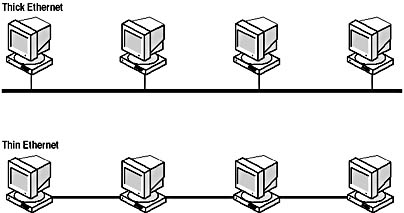
When any one of the computers on the network transmits data, the signals travel down the cable in both directions, reaching all of the other systems. A bus network always has two open ends, which must be terminated. Termination is the process of installing a resistor pack at each end of the bus to negate the signals that arrive there. Without terminators, the signals reaching the end of the bus would reflect back in the other direction and interfere with the newer signals being transmitted.
Run the c02dem02, c02dem03, c02dem04, c02dem05, and c02dem06 videos located in the Demos folder on the CD-ROM accompanying this book for a demonstration of bus topology communications, signal bounce, and termination.
The main problem with the bus topology is that a single faulty connector, terminator, or break in the cable affects the functionality of the entire network. Signals that cannot pass beyond a certain point fail to reach all of the computers beyond that point. In addition, the break in the cable is also unterminated. On the half of the network that does receive the transmitted signals, the data can be affected by reflected signals. This is one of the primary reasons that bus networks are almost never used nowadays.
Run the c02dem07 and c02dem08 videos located in the Demos folder on the CD-ROM accompanying this book for a demonstration of a bus topology failure.
While the bus topology has the computers in a network logically connected directly to each other, the star topology uses a central cabling nexus called a hub or concentrator. In a star network, each computer is connected to the hub using a separate cable, as shown in Figure 2.2. Most LANs installed today use the star topology. LANs can use several different cable types, including various twisted pair and fiber optic configurations. The main advantage of the star network is that each computer has its own dedicated connection to the hub. If a single cable or connector should fail, only one computer is affected.
Run the c02dem09, c02dem10, and c02dem11 videos located in the Demos folder on the CD-ROM accompanying this book for a demonstration of star topology.
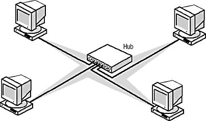
The disadvantage of the star topology is that an additional piece of hardware, the hub, is required to implement it. If the hub should fail, the entire network goes down. However, this is a relatively rare occurrence, since hubs are usually found in a protected environment, such as a data center or server closet.
As far as signal transmissions are concerned, a ring network is like a bus in that each computer is logically connected to the next. The difference is that in a ring network the two ends are connected instead of being terminated. This enables a signal originating on one computer to travel around the ring to all of the other computers and eventually back to its point of origin. Networks such as Token Ring, which use token passing for their media access control (MAC) mechanism (as explained in Lesson 2: The OSI Reference Model, in Chapter 1, "Networking Basics"), are wired using a ring topology. The most important thing to understand about the ring topology, however, is that it is strictly a logical construction, not a physical one. Or, to be more precise, the ring exists in the wiring of the network, but not in the cabling.
When you look at a network that uses the ring topology, you may be puzzled to see what looks like a star. In fact, the cables for a ring network connect to a hub and take the form of a star. The ring topology is actually implemented logically, using the wiring inside the cables. Ring networks use a special type of hub, called a multistation access unit (MAU), which receives data through one port and transmits it out through the next. This process continues until the MAU has transmitted the signals to each computer on the ring. If you were to remove the wires from the cable sheath, you would have a circuit that runs from the MAU to each computer and back to the MAU, as shown in Figure 2.3.
Run the c02dem12, c02dem13, c02dem14, and c02dem15 videos located in the Demos folder on the CD-ROM accompanying this book for a demonstration of the ring topology.
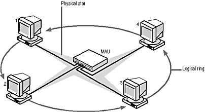
The design of the star topology used by the ring makes it possible for the network to function even when a cable or connector fails. The MAU contains special circuitry that removes a malfunctioning workstation from the ring. By comparison, a network that is literally cabled as a ring would have no MAU, but that would cause the network to cease to function in the event of a cable failure.
Run the c02dem16 video located in the Demos folder on the CD-ROM accompanying this book for a demonstration of a ring topology failure.
There are three primary types of cable used to build LANs: coaxial, twisted pair, and fiber optic. Coaxial and twisted pair cables are copper-based, while fiber optic cables use glass or plastic conductors.
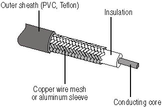
Coaxial cable is so named because it contains two conductors within the sheath. Unlike other two-conductor cables, however, coaxial cable has one conductor inside the other. This is illustrated in Figure 2.4. At the center of the cable is the copper core, which actually carries the electrical signals. The core can be solid copper or composed of braided strands of copper. Surrounding the core is a layer of insulation, and surrounding that is the second conductor, which is typically made of braided copper mesh. This second conductor functions as the cable's ground. Finally, the entire assembly is encased in an insulating sheath made of PVC or Teflon.
There are two types of coaxial cable that have been used in local area networking: RG8, also known as Thick Ethernet, and RG58, which is known as Thin Ethernet. These two cables are similar in construction but differ primarily in their thickness (0.405 inches for RG8 versus 0.195 inches for RG58) and in the types of connectors they use (N connectors for RG8 and BNC connectors for RG58). Both cable types are wired using a bus topology.
Coaxial cable is used today for many applications, most noticeably on cable television networks, but it has fallen out of favor as a LAN medium. This is due to the bus topology's fault-tolerance problems and the size and relative inflexibility of the cables, which make them difficult to install and maintain.
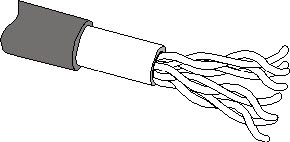
Twisted pair cable wired in a star topology is the most common type of network medium used in LANs today. Most of the LANs installed today use unshielded twisted pair (UTP) cable, but there is also a shielded twisted pair (STP) variety for use in environments more prone to electromagnetic interference. UTP cable contains eight separate conductors, as opposed to the two used in coaxial cable. Each conductor is a separate insulated wire, and the eight wires are arranged in four pairs of twisted conductors. The twists prevent the signals on the different wire pairs from interfering with each other (called crosstalk) and also provide resistance to outside interference. The four wire pairs are then encased in a single sheath, as shown in Figure 2.5. The connectors used for twisted pair cables are called RJ45s; they are the same as the connectors used on standard telephone cables, except that they have eight electrical contacts instead of four.
Twisted pair cable has been used for telephone installations for decades; its adaptation to LAN use is relatively recent. Twisted pair cable has replaced coaxial cable in the data networking world, because it has several distinct advantages. First, because it contains eight separate wires, the cable is more flexible than the more solidly constructed coaxial cable. This makes it easier to flex, which simplifies installation. The second major advantage is that there are thousands of qualified telephone cable installers who can easily adapt to installing LAN cables as well. In new construction, telephone and LAN cables are often installed at the same time, by the same contractor.
UTP cable comes in a variety of different grades, called "categories" by the Electronics Industry Association (EIA) and the Telecommunications Industry Association (TIA), the combination being referred to as EIA/TIA. These categories are listed in Table 2.1. The two most significant UTP grades for LAN use are Category 3 and Category 5. Category 3 cable was designed for voice-grade telephone networks and eventually came to be used for Ethernet. Category 3 cable is sufficient for 10 Mbps Ethernet networks (where it is called 10BaseT), but it is generally not used for Fast Ethernet (except under certain conditions). If you have an existing Category 3 cable installation, you can use it to build a standard Ethernet network, but virtually all new UTP cable installations today use at least Category 5 cable.
Table 2.1 EIA/TIA UTP cable grades
Category 1 |
Used for voice-grade telephone networks only; not for data transmissions |
Category 2 |
Used for voice-grade telephone networks, as well as IBM dumb-terminal connections to mainframe computers |
Category 3 |
Used for voice-grade telephone networks, 10 Mbps Ethernet, 4 Mbps Token Ring, 100BaseT4 Fast Ethernet, and 100VG AnyLAN |
Category 4 |
Used for 16 Mbps Token Ring networks |
Category 5 |
Used for 100BaseTX Fast Ethernet, SONet, and OC-3 ATM |
Category 5e |
Used for Gigabit (1000 Mbps) Ethernet protocols |
Category 5 UTP is suitable for 100BaseTX Fast Ethernet networks running at 100 Mbps, as well as for slower protocols. In addition to the officially ratified EIA/TIA categories, there are other UTP cable grades available that have not yet been standardized. A cable standard called Level 5 by a company called Anixter, Inc. is currently being marketed using names such as Enhanced Category 5. This cable increases the bandwidth of Category 5 from 100 to 350 MHz, making it suitable to run the latest Gigabit Ethernet protocol at 1,000 Mbps (1 Gbps). Level 6 cable increases the bandwidth even further.
Shielded twisted pair cable is similar in construction to UTP, except that it has only two pairs of wires and it also has additional foil or mesh shielding around each pair. The additional shielding in STP cable makes it preferable to UTP in installations where electromagnetic interference is a problem, often due to the proximity of electrical equipment. The various types of STP cable were standardized by IBM, who developed the Token Ring protocol that originally used them. STP networks use Type 1A for longer cable runs and Type 6A for patch cables. Type 1A contains two pairs of 22 gauge solid wires with foil shielding, and Type 6A contains two pairs of 26 gauge stranded wires with foil or mesh shielding. Token Ring STP networks also use large, bulky connectors called IBM data connectors (IDCs). However most Token Ring LANs today use UTP cable.
Fiber optic cable is a completely different type of network medium. Instead of carrying signals over copper conductors in the form of electrical voltages, fiber optic cables transmit pulses of light over a glass or plastic conductor. Fiber optic cable is completely resistant to the electromagnetic interference that so easily affects copper-based cables. Fiber optic cables are also much less subject to attenuation than are copper cables. Attenuation is the tendency of a signal to weaken as it travels over a cable. The longer the cable, the weaker the signal gets. On copper cables, signals weaken to the point of unreadability after 100 to 500 meters (depending on the type of cable). Some fiber optic cables, by contrast, can span distances up to 120 kilometers without excessive signal degradation. This makes fiber optic the medium of choice for installations that span long distances or that connect buildings on a campus. Fiber optic cable is also inherently more secure than copper, because it is not possible to tap into a fiber optic link without affecting the normal communication over that link.
A fiber optic cable, as illustrated in Figure 2.6, consists of a clear glass or clear plastic core that actually carries the light pulses, and is surrounded by a reflective layer called the cladding. Around the cladding is a plastic spacer layer, a protective layer of woven Kevlar fibers, and an outer sheath.

There are two primary types of fiber optic cable, called singlemode and multimode. The difference between the two is in the thickness of the core and the cladding. The measurements are the primary specifications used to identify each type of cable. Singlemode fiber typically has a core diameter of 8.3 microns, and the thickness of the core and cladding together is 125 microns. You will generally see this referred to as 8.3/125 singlemode fiber. Multimode fiber is usually rated as 62.5/125.
Singlemode fiber uses a single-wavelength laser as a light source, and as a result, it can carry signals for extremely long distances. For this reason, singlemode fiber is more commonly found in outdoor installations that span long distances, such as telephone and cable television networks. This type of cable is less suited to LAN installations because it is much more expensive than multimode and has a higher bend radius, meaning that it cannot be bent around corners as tightly. Multimode fiber, by contrast, uses a light emitting diode (LED) as a light source instead of a laser and carries multiple wavelengths. Multimode fiber cannot span distances as long as singlemode, but it bends around corners better and is much cheaper.
Installing fiber optic cable is very different from any copper cable installation. The tools and testing equipment required for installation are different, as are the cabling guidelines. Generally speaking, fiber optic cable is quite a bit more expensive than twisted pair or coaxial in every way, although prices have come down in recent years.

Match the applications in the left column with the network cable types in the right column that best suit them.
1. Uses the bus topology |
a. UTP |
2. Used for the original Token Ring networks |
b. Singlemode fiber optic |
3. Used for Gigabit Ethernet networks |
c. Shielded twisted pair |
4. Contains eight wires |
d. Coaxial cable |
5. Used for LANs that span long distances |
e. Category 5e UTP |
6. Uses a laser to generate signals |
f. Multimode fiber optic |